3D information can still be extracted from an image taken by an imaging device such as a camera. By knowing the physical processes that took place in converting a 3D information into a 2D. A location of an object in a real world can be represented by a three dimensional vector. However, in computer graphics, to further help the modeling of the object, the coordinates must need to be homogeneous. It is simply transforming a nx1 vector into an (n+1)x1 vector and multiplying the real world coordinates with the nth element. In the image space, since it is only limited to 2 dimensions, representing it in homogeneous coordinates will change it from a 2x1 vector into a 3x1. Since image representations of the real world are augmented vector space vectors, a non-linear relationship between the image location and the real world location can be obtain, and it is given by,

where Pi are the homogeneous coordinates of the object in the image, Pgo, on the other hand are the homogeneous coordinates of the object in the real world, and A is the transformation matrix, intrinsic to the imaging device, that involves a translation matrix, that gives the translation of the object origin of the real world coordinate system to the image plane origin, and a rotational matrix, that gives the rotational matrix needed to coincide the real world coordinate to the image-centric coordinate system.
From the equation given above, we can solve the image coordinate of a the object in terms of the the real world coordinates of the object. The image coordinates are given by,

Now by setting a34 = 1, we can separate the a's and solve through systems of linear equations. The separated a's are given by the equation,

From the equation above, for a single point in an image plane, we have 11 a's that are unknown. To solve this problem, we must have points greater than the number of unknowns.
In calibrating imaging device used in capturing the image, we used a Tsai grid, shown in Figure 1, to get the intrinsic a's.

Figure 1. Tsai grid used in calibrating the camera used in taking this picture.
The size of each square block are known, so from this image, we can get 11 real world points that specifies the xo, yo, and zo, and also from these points we can specify the image location. The previous equation can be represented by,

where Q is the left most matrix from the previous equation, a is the matrix of a's, and p is the right most matrix in the previous equation. The a's can be solved by the second equation showed above. To create Q, we must stack the left most matrix we obtained from each point. The same must be done to the right most matrix so that p can be constructed.
Now that we have the a's of the camera, we can now transform image coordinates to real world coordinates and vice versa. To test if the a's obtained are correct, a real world coordinate was picked and was then displayed on the image. Table 1 shows the real world coordinates used for the verification of the calibration and Figure 2 shows the transformed points.
Table 1. Real world coordinates and its corresponding image coordinates.

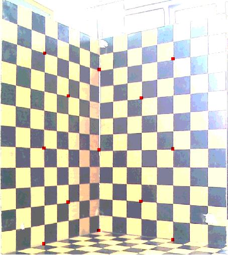
Figure 2. Tsai grid displayed with the transformed real world coordinates.
In summary of this article, we have calibrated an imaging device and verified if the calibration is correct by transforming a real world coordinate to an image coordinate.
Reference
- Dr. Soriano. Applied Physics 187 activity 8 manual.
No comments:
Post a Comment